The Name is Type… Prototype
Before any serious construction on the board can begin, the basic premise of lighting a translucent rectangle of plastic with an LED needs to be vetted. So, it was time to go to the workshop and figure out how to best cut tiny pieces of plastic and assemble them into a workable shape. After a few false starts with the table saw and miter saw, I figured out a few approaches that seemed reasonably safe, and which did not involve flinging plastic cuttings across the garage at high velocity.
Once I had some pieces of approximately the right size prepared, I assembled a prototype test box using that most familiar of all quality construction tools, Scotch tape. (Did you know Scotch tape was named based on an ethnic slur, saying that someone’s boss was being cheap? Go look it up somewhere.) Hey, it did the job. Hooked up an RGB LED, wired some reasonable colors using different resistors, put the box over it, and… oh dear. Even using a diffused LED lens, it’s still very obvious that there are three separate color elements under the plastic, and the top of it is lit very differently than the bottom. Well, this won’t do at all.
After some research, it seems that the best solution to this is to mount the LED to the side of the box, rather than the bottom, then coat the inside of the box with a white material to reflect the light, giving it a much larger space in which to mix. So, after a visit to the trusty drill press and application of some very expensive typing paper with more Scotch tape, my side fire test was ready. This time, I had much more pleasing results, with reasonable color mixing and no particular hot spots. I still needed to keep the LED from being too close to the top of the box, or it would give a hot spot, though, so I can’t make the board as completely thin and streamlined as I had perhaps hoped. This is still well within the realm of reason, though.
Next step is to actually light the prototype box using an LED powered by the LED driver chip. Until that test is performed, I can’t be sure that a single LED will be sufficient to light the whole space. If I need to light two per space, things may get complicated, so let’s hope that’s not a problem.
Control Freak
Controlling one LED with a Netduino or other microcontroller is easy. Controlling two, three, four, likewise simple. How about controlling 143? That’s about how many I’ll need for this project, and that’s a lot more digital outputs than any microcontroller I know of can handle. So, what can we do? Obviously other projects have controlled large quantities of LEDs, so we need to figure out what they’re doing and whether it will help.
After discussing the problem with coworkers, we discovered the joy of RGB LED cubes. If you haven’t seen them, use your Google skills and be impressed. The short version is that one microcontroller is managing a 6 x 6 x 6 (or whatever size) cube of LEDs, putting up all sorts of cool patterns. This is typically accomplished through a bit of electronic trickery, where the microcontroller is only actually controlling one slice of the LEDs at a time. Because humans experience a phenomenon known as “persistence of vision”, it appears that all the LEDs are lit simultaneously, even though only a fraction are actually on at any given time. The same trick was used back in the days of CRT monitors and TVs, where a single point of light was all that was actually illuminated at one time; your brain (and some slow-fading phosphors) did the rest.
For this project, though, I wasn’t quite sure relying on persistence of vision would get me where I wanted to be. I’m trying to illuminate plastic with these LEDs, which means the overall light is getting dispersed and diminished. For that, I want to keep as much full power, full time brightness as possible, so I want every LED to be on full time if I want it on. Some further links and research turned up a class of ICs called LED drivers, which (as the name implies) drive LEDs. You tell the chip “turn on LEDs 1, 5, 8, and 12”, and it’ll keep those lit until you tell it otherwise.
After looking around, I found the TLC5490 (and TLC 5491) chips seemed like good candidates with existing Netduino support. Each of them can handle 16 LEDs, and since I need to run 143 (remembering that the red, green, and blue channels are all independent) I sent out an order for 10 of them. (Nine would be okay, but who doesn’t order at least one spare?) A big benefit of the chip is that it supports built in Pulse Width Modulation (PWM), which lets you adjust the brightness of the LEDs. This is actually a technique that goes back to the persistence of vision thing, so that if I want the LED to be 50% brightness, the chip will handle having it be on 50% of the time and off 50% of the time. It’s not perfect, since the human eye only begins to detect dimming at a lower percentage, but it’ll work for what I want. (Also, you can daisy chain these guys together, which means I can run all nine or ten of them from one set of control lines. Sweet!)
The chip also requires an external grayscale clock signal. I could run that from the microcontroller, but that seems like unnecessary work, so we’re going to try running it from an external chip. One annoying thing about the TLC5940/1 is that it has a fundamental cycle of 4096 pulses on the grayscale clock. After it’s run through its cycle, you actually have to send the chip a blank command, release it, and let it start on a fresh count of 4096. To handle this, I went to our local electronics supplier, Intertex, and grabbed some 4060 binary counter chips. I found out later that they have a built-in oscillator circuit, so theoretically all I need to do is hook up a resistor and capacitor to it, and I should be able to generate my grayscale clock straight out of the chip.
(Foreshadowing: That last bit didn’t work to my satisfaction.)
The Gathering (of Materials)
This will be an ongoing process, acquiring all the stuff needed to make this project a reality. I’m actually back-dating a few of these posts as I’m starting the documentation process, so I may have skipped a few steps here and there. Anyway, here’s some of the stuff that’s already come together to start making this happen.
- Acrylic, and lots of it! Turns out a local plastics supplier, Regal Plastics, has a scrap pile. You can go rummage around and get their leftovers for cheap. I picked up a variety of different plastics including opaque black, translucent white, and transparent clear for about $8.00. Hopefully I have enough for what I need to do, but even if not, it gives me lots of material to test with and decide what will work best.
- Acrylic solvent adhesive. Wanted to get Weld-on from the plastic supply house, but they were out of applicators. I ended up getting some adhesive from a local hobby shop instead. Either way, the stuff actually causes the two acrylic pieces to fuse together into one, giving a nice strong joint.
- RGB LEDs. Got a few packs from eBay. Probably have more of these than I need, but wanted to have spares and extras in case my plan of one LED per space turned out to be infeasible.
- White LEDs. No sense in wasting an RGB LED on a section of the board that has a native color, like the property bars or the In Jail section. Just light those with a simple white LED and move on with life.
- Netduino microcontroller board. I’ve done raw PIC programming before and played with an Arduino a bit, and this time I’m going to try something different. A coworker was doing a project with this, but realized he needed a more powerful board, so I got this from him at a discount. May as well see if it’ll do the job I want!
- Two line LCD display. Rather than have a huge switch bank, we want to reduce the number of controls needed for this. To do that, we’ll need to provide user feedback about what those controls are doing. Two lines of LCD display seem to be quite sufficient for my purposes.
- Lots of miscellaneous electronics parts. I’ve been projecting for a while now, so there’s lots and lots of goodies in my bins already. Many of them should be useful in this process.
I also have picked up a couple of plastic-specific saw blades for my table saw and miter saw. They’ve worked reasonably well so far, but I’m hoping that I’ll learn even more about how to best use them to get nice, solid, clean cuts in this material. The less sanding and edge-polishing I have to do, the better.
The Best-Laid Plans
So having “helped” build a lighted board before, what do I want to get out of a newer board now? Well, there were several problems in the original that I’d like to overcome, and there are many features that simply weren’t within what we could reasonably accomplish given the technology that now seem possible.
So, technology aside, what were the big design flaws last time around? Here are the ones that seemed most obvious to me.
- Light leakage between spaces
- Dark areas at the top and bottom of each space (where the wood support for the track blocked light)
- Uneven space sizes/shapes
- Poor felt quality/poor logo quality
There’s plenty of other problems as well, both in original concept and execution, but I’ll let those pass. It was something fun for my Dad and me to do together. I actually have a newborn boy (which is why this build is going to take much longer than it otherwise might need to) but I just can’t bear to put the idea on a shelf for as long as it would take for him to understand and enjoy what’s going on. (Once he’s older, I’ll show this to him and ask him what other ideas he’d like to see come to life!)
With those problems in mind, what new features are possible given the current state of technology?
- Multicolor LED space lighting
- Independent property/color bar lighting
- Not having a huge bank of 40 switches to control everything
- Not using electrical tape to secure wire connections
An ambitious project to be sure, and the most complicated build I’ve done to date. (I suppose the IIDX controller was pretty complex, but this will probably be more difficult even than that.) So what materials and techniques shall we use to accomplish these goals?
- Solid black acrylic space dividers to reduce/eliminate light leakage and provide visible lines
- Translucent white acrylic panels for each game space to diffuse light evenly
- Thin or transparent supports for the spaces to eliminate dark edges
- RGB LEDs for each space to provide a wide variety of possible colors
- Independent white LEDs on each colored property bar and the In Jail space
- Microcontroller brain to run everything using a more limited control set
- LED driver ICs so we don’t need to have 160 or so individual digital outputs from the microcontroller
Several problems are not yet figured out, but I’m assuming I’ll be able to tackle those once I figure out what they are. Should be fun (and frustrating)!
Every Story Has a Beginning
So, why are we here? Simple concept, really. I want a lighted Monopoly board. Why? Good question, but really just because I do. I’ve been a long time fan of Monopoly, playing since I was… well, I don’t know how old but I’ve played as long as I remember. Certainly earlier than it’s recommended, anyway. Nowadays, I can’t get people to play with me because (they say) I’m just too good. Frankly, I can’t remember actually playing anybody around here in the first place, so I don’t know what they would base that on. They probably just remember the interminable games that everyone grew up playing. If you play the game right, it does end, I promise!
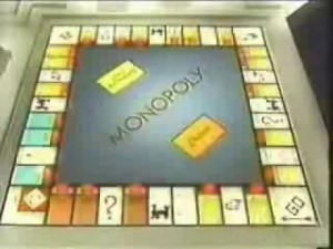 Anyway, one of the things I remember from childhood was a brief game show version of Monopoly. It only ran for one summer, but boy did I love to watch that. The gameplay was completely different from the actual game, but that didn’t matter. Know why? Because they had an awesome, gigantic, lighted game board. My impressionable little mind was set: I had to have one of my own. Perhaps a more reasonable size, though.
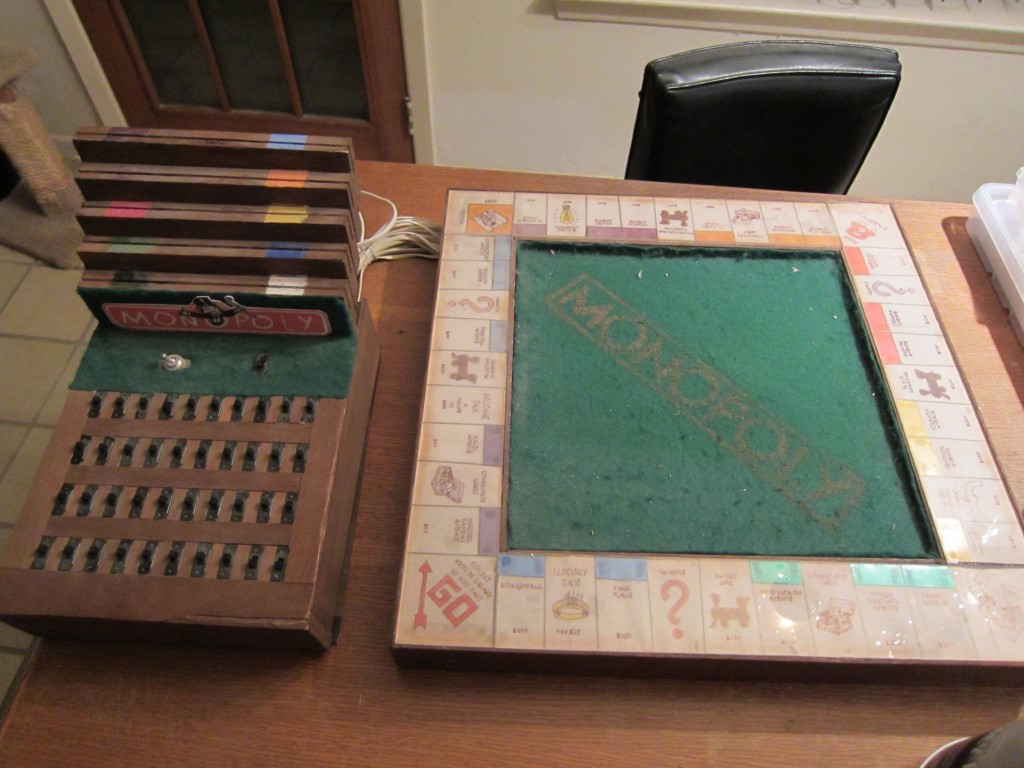
My Dad was a pretty able woodworker, so when I mentioned this idea as a kid, he took it as an opportunity to do a project with me. I like to say we built it together, but I’m pretty sure he did all the building while I watched and dreamed about how awesome it would be. Of course, back then we didn’t have access to nearly the same amount of cool stuff for making as we have now, so rather than using spiffy LEDs and microcontrollers, our solution was based on Christmas tree lights and a huge bank of switches. But you know what? It worked.
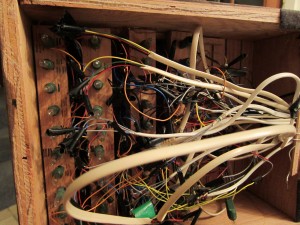 Note that I do say “worked”, past tense. After digging this up, I decided to try to turn it on. Didn’t work straight away, so I opened up the control panel to figure out why. After looking at how we actually made this “work”, I quickly decided that for safety’s sake, I would never be trying to turn it on again. Somehow, connections carrying line voltage and made with electrical tape just don’t give me much confidence.
You may also note the surprising number of lights inside the control box itself. Well, when you’re dealing with 1980’s Christmas tree lights, it turns out that lighting up one light with the same current you otherwise would use for 40 makes that one light burn very brightly. To combat this, clearly you should always have 40 lights burning. So, 40 in the board, 40 in the box, and every switch changes current from using one in the board to one in the box instead, or vice versa. Crude, but effective, and it kept all the lights a consistent level.
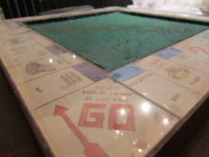 The board itself was pretty basic construction, with a plywood base and sides, a hollow center to run wiring, and acrylic panels to form the actual game tracks. The spaces were all hand drawn by yours truly on tracing paper from an actual game board. Unfortunately, the years have not been kind to the paper or ink, and most of the spaces are faded and discolored badly. The color bars on the properties were cut out of a variety of plastic films and layered to build up the appropriate colors.
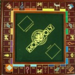 The center of the board had a felt surface, with a gold Monopoly logo inspired by the Franklin Mint board. Oh, how I longed for that set, but there was no way I’d ever be able to afford it. I might actually try to grab one if a good deal comes by on eBay some day, but back then it was the height of luxury to even consider. This helped me get one tiny step closer to having something like it.
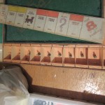 The board was lighted, as mentioned before, with Christmas tree lights. Each light was mounted under the appropriate space, and when the switch was thrown, would illuminate the tracing paper of the appropriate spot. The spaces were divided using a simple cardboard divider, which kept most of the light where it belonged, but was a little too translucent to do a really good job. The board and panel were connected with a bundle of telephone wires, with one pair dedicated to each light. In retrospect, there were many things we could have done that would have made this better, and it’s with an eye towards those improvements that I’ve embarked on this quest to build an even better lighted Monopoly board.
-
Archives
- November 2012 (2)
- October 2012 (1)
- September 2012 (4)
- July 2012 (2)
- June 2012 (7)
- May 2012 (6)
- April 2012 (5)
-
Categories
-
RSS
Entries RSS
Comments RSS
