Texas Hold ‘Em
Finally soldered up one of the secondary driver boards. Lots of little connections to make, but I’ve gotten good enough with the iron that it went pretty quickly. Got things hooked together this morning to give it a test, and it actually went pretty well. Not perfectly, though, which is somewhat concerning. The LEDs on the secondary boards lit appropriately, but sometimes, randomly, came back on during phases they should have remained off. There are a couple of possibilities that I can think of here. Both of them end up coming down to the same thing: Something is a little bit off on the reference voltage and the signal voltage passing between the chips.
I don’t have this issue on the single chip on the timing board, which is driven by the Netduino directly, but once it cascades from one chip to the next, and goes to a board driven by my voltage regulator chips, it starts acting up. So, could be the chips aren’t outputting quite as much voltage as they should, or the power supply isn’t quite as steady as it needs to be. My bet is on the latter, since these chips are used by who knows how many people for how many applications worldwide. They wouldn’t just not work as designed. I haven’t included any capacitors in my power circuit yet, so I’m hoping that adding those will help out.
Of course, the second possibility is that the instability is just being caused by the fact that I have things in a sort of temporary test rig setup. If I were to go ahead and finish the soldering, make proper connections between the boards, and hook up the board itself, maybe it’d all just work. But if it didn’t, how deep in a hole would I be for solving the problem at that point? Am I really ready to go all in on this? Or do I get some caps on order and retest first?
By the Power of Grayskull
Not a whole lot of progress recently, as it’s difficult to find time to work on the project with other various life things going on, but a little more forward movement today. I knew from reading up that it was likely the Netduino wouldn’t be able to power all the LED driver chips by itself; the LEDs would end up drawing more current than the Netduino is designed to supply. So, I ended up getting some voltage regulation chips. Spent a little time today building up a PCB to hold those chips, soldered it together, and was pleasantly surprised when I was able to sub that into my current setup and run the timing/LED driver PCB on power from that board rather than from the Netduino. No reason it shouldn’t have worked, but I’m trained to expect things not to behave as I want on the first try. It’s nice to be surprised once in a while.
Now I just have to wait to see how it turns out this was actually a failure, when something bites me down the road.
Fix-It Felix, Jr.
Finally got around to troubleshooting the timing circuit, and it looks like it’s up and running successfully now. Hooray! Turned out there were two problems: in the schematic, I had accidentally swapped a connection of the grayscale clock and the serial clock; and I had left the latch pin disconnected somehow. I’ll need to go double-check the other board now to make sure these same errors didn’t occur there, but even if they did, I can fix it with extra wires if needed. Regardless, it’s heartening to finally have this part of the project back under control.
Next steps could involve any of: Trying to connect this to the board itself, working on the control software, or wiring up the secondary boards. No idea which I want to tackle first.
Philosopher World
Well, I finally made the time to solder up one of the boards I ordered and, not too surprisingly, it didn’t work off the bat. I noticed a flaw in the schematic as I was looking to see how everything should be wired up, and was able to fix that, but the overall fact remains that even with the fix, the board didn’t do its job. So now, I have the long troubleshooting process to look forward to. This will probably tell the tale of whether I actually finish this project. This is the kind of setback that can really sap the desire to move forward, because you feel like you’re so close to a breakthrough, but suddenly get a roadblock set before you that may take weeks to clear. It’s not like I’ve had a lot of time to devote to the project at all lately, so it’ll be interesting to see whether I can manage to solder on. (See what I did there?)
Ethereality
Got the PCBs in, but before playing with those, I finally had a chance to test some of the wireless communication bits. Seemed like the XBees were set up to be as easy to use as possible, and that’s the experience I ended up having. Did a little bit of digging to confirm what chunks of code I needed, but pretty quickly got it up and running.
The Netduino that I’ve been using all this time is still running the LED driver, and now has a countdown cycle that I can trigger with the on-board button which lights a number of LEDs, then turns one off each 1/4 second. I then added an XBee Series 1 to it using an Arduino shield, and put in a bit of code to also trigger the countdown cycle any time the XBee receives data.
That meant it was time to break out the Netduino Plus, hook up an XBee, and have it transmit a single character when its on-board button is pressed. At first I worried it hadn’t worked, because it didn’t seem to respond to my first button press, but later presses worked exactly as desired. Press button on one board, watch LEDs controlled by other board light up then die down. Pretty dang cool.
Side note here is that this is the first time I’ve run the LED board off battery power. Got a lot of flicker on them in this configuration, unfortunately. That being said, it’s working on 4 AA cells, whereas the final is probably going to be running 4 D cells. Hopefully that difference will help even out the power and make things shinier. If not, I’ll have to spend more time figuring out the power solution than I’d hoped.
I Don’t Want to Go on the Cart!
Things have been a little slow of late, but finally making a tiny bit more progress. Finally figured out an issue I was having with the LED driver chips, namely that I was running them on 5V source but giving them 3.3V signals. That caused the serial communication to work sometimes, but not always. After adjusting the source voltage down to the 3.3V rail, it started working properly with multiple chips. Given that, I’ve ordered some PCBs to see how I can do on actually wiring everything up. If this goes well, I’ll have to start looking at the actual board and control housings, and figure out how to connect them. My initial plan was a simple Cat-5 connection, but I’ve started looking at some wireless communication stuff that’s intriguing. It’d be quite nice to not have the controls tethered to the board itself, and would really free the thing up to be set up however works best. Will keep looking into possibilities.
Taste the Rainbow
Got the new breadboard in as a birthday present (thanks Dee!) and finally got the circuit transferred over. It immediately appeared to be better, as the behavior was more consistent, even if not exactly what I wanted. Initially, I could tell during the pulse cycle exactly when the LEDs were at full intensity, and exactly when they were off. The times in between, however, were all identical. After looking over schematics and pinouts, though, I discovered a couple of swapped connections. Amazing how not hooking things up in the right order can make it not work.
After fixing the incorrect wiring, the circuit began acting as expected, although at some intensities the LEDs had a very annoying flicker. Regardless, I carried on, but the flicker continued to annoy. I eventually figured I should swap out my oscillator chip for a faster one, but realized I had the fastest one I ordered already in, at 3.0 MHz. So, figuring I had nothing to lose, I swapped in the slower 1.5 MHz chip, and suddenly the flicker was completely gone! Guess the higher frequency was just a little too much for the LED driver running at 5V off the Netduino.
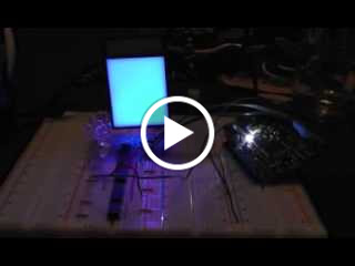
With the flicker gone, I finally started to play with some actual color values, and set my prototype space back on the RGB LED. As I’m typing this, I’m watching it cycle as follows: Off, white, red, green, blue, yellow, magenta, teal, and a repeat of the colors in a much darker, muted version. I’m hoping to allow the colors to be customized while playing, but for now this is a really great milestone, as it’s showing a wide range of colors using the type of materials I’m building with, and the blending on the actual surface of the space is really quite pleasant. This gives me the highest of hopes for the results of the full build.
(Click for video if you’re interested)
A Touchy Subject
Finally got a chance to link in the Or gate as the original schematics showed, and that seemed to help alleviate the problems I was seeing, but another problem showed itself. I’d seen something like this before, but tonight it was more apparent what the behavior is, if not the cause. It seems like there’s some strange issue with my breadboard, causing the behavior of the circuit to change depending on whether I am physically touching the top of the surface of the board or not. I tried grounding it, but that just made it stop working all together. So, touch the surface, and it works, stop touching, it stops working. Something’s definitely fishy, and I can’t really tell if I’ve wired something wrong or if I just need to replace the breadboard. Will probably try something else soon, even if it’s just soldering the works together.
Follows Directions
Got the new oscillators in the mail today, and swapped them into the circuit. Much more reliable behavior, but still wasn’t quite as I expected. So, I finally buckled down and went back to one of my original sources and made a stronger effort to faithfully replicate the circuit as presented. Well, nearly faithfully. I haven’t got the Not or Or gates in place, but seem to be doing okay enough for the moment. I also connected the line running Blank on the TLC5941 to also hit the Reset input on the 4060 so that I can immediately restart the cycle of 4096 rather than waiting for the counter to get back up to that point again. May not be completely necessary, but I wanted to maintain the full range of brightness possible. Regardless, some measure of success! Hooray!
Still a few glitches in the system. When I tried to only light a few LEDs, the others would periodically flash on briefly. I expect this may be due to my ignoring the warning to only send the XLAT command while Blank is active. To do that, I’ll need to put that Or gate in place. Should have a few laying around somewhere. Also, I should run some tests on just leaving the Blank set for longer; that could actually give me greater brightness control if, as I suspect is the case, the whole Persistence of Vision thing means that brightnesses between 50% and 100% are virtually indistinguishable. Should be some good testing, regardless. For tonight, though, the core lesson of “Get what you’ve read about working before tinkering with it” is once again learned.
(And promptly forgotten.)
Going Back and Forth on This
So, crystals came in. Because I failed to actually check the Amazon listings very carefully, I just ordered the first crystals I saw, which were marked as 16.0 MHz. After the order was placed and on the way, I see that the chip I’m using may not be happy with anything more than 3.0 MHz. Oops. Well, may as well try it anyway.
Hooked up the crystal in the circuit as demonstrated in the previously discussed page, and was pleasantly surprised to see the timing LED firing much more quickly than with the RC circuit. Not only that, but the fact that it was firing at all was a positive sign! Maybe it’d work with this frequency after all! Well, let’s just connect the rest of the circuit back up and see what happens.
Well, better results, but far from acceptable. I can see the PWM beginning to occur, but it’s not really working, so much as turning the LEDs on and off… very… slowly… Drat. Well, I can play around with some resistor and capacitor values to see what I can do, but that’s just not going to cut it. I hooked up a logic analyzer and saw some interesting results. The analyzer can only sample at 24 MHz, so I can’t expect to get a regular 16 MHz signal fully captured, but I should be able to see something. And something I did see. A very erratic signal, with a short burst of regular pulses that measured around 7 kHz, followed by long stretches of no pulses whatsoever, then another burst.
This means one of two things the way I figure. Possibility A is that I’m really just not reading it well, and the signal is fine, and I’m just missing 95% of the pulses. Possibility B is that something is still very wonky with the circuit, possibly due to the load of the other chip, and it’s just too fragile and sensitive to be reliable in the current configuration. Considering that I also was tracing one of the higher count lines, and its pulses only seemed to occur when the bursts I did record occurred, I’m thinking option A is far more likely.
So, another timing option come and gone. I could go ahead and order another batch of 50 crystals for a different frequency, but instead I’m going to turn to Digi-Key, who a coworker conveniently pointed out is willing to ship USPS first class mail for cheap. I’ve got three different frequencies of actual oscillator chips on order, which I’m hoping will be far more resilient to the vagaries of my circuit that these RC and crystal configurations have been.
-
Archives
- November 2012 (2)
- October 2012 (1)
- September 2012 (4)
- July 2012 (2)
- June 2012 (7)
- May 2012 (6)
- April 2012 (5)
-
Categories
-
RSS
Entries RSS
Comments RSS