Time for Reflection
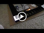
It’s taken several evenings of work, but finally got all the white diffuser/reflector pieces in place. The really nice thing about that is it adds some not insignificant structural support to the piece. Carrying it around doesn’t feel nearly as fragile as before. Not a whole lot else to report, so have a couple of shots with all the reflection in place.


The L-Word. I Mean Space. The L-Space
It’s finally time to start actually putting the spaces together and making things fit. Decided to start with the corners because they’re both the easiest and hardest spaces to do. Easiest because they’re the deepest ones I’ve designed. Hardest because of this:
 Silly me, wanting to be all perfectionist, decided that Jail and Just Visiting are truly two independent spaces, which means they have to light up separately. Since the jail is permanently orange, it’ll get a simple white LED with appropriate color graphics, but I still wanted the Just Visiting side to get a full RGB treatment. Not because you can buy the property, but because it looks that much cooler if I can do color chase patterns around the board. Anyway, this meant I had to figure out how to position that single LED so it could light up the full L shape without bleeding over into the In Jail square.
The result was a 45 degree angle piece that runs just along the JAIL text, below the floor of the Jail space itself. A bit of electrical tape helped ensure that no excess light from the LED mounted there would sneak up into the other space. After using quite a lot of plastic cement, things were finally ready for a test. Again I have a video, and again it shows up much hotter and whiter in the video than it does in real life, but I think you can at least see that full space is getting lit, and Jail is staying nice and dark.
Flame Off!, or, Like Sands Through the Hourglass
I’ve been pretty anxious to start putting together the surface supports for the board, but managed to convince myself to hold off until I figured out how I could clean up the exposed surfaces of the black acrylic. What I’ve always read is that the single best way to finish acrylic edges is by using flame polishing. Basically, move a torch quickly along the edge so the acrylic very briefly melts, then reforms a glossy, polished edge.
Great theory.
I went out to get a torch, which may be useful for other things later, and tested it out. Sure enough, it can melt the plastic, but there was one tiny problem. The acrylic I have is so thin the process caused warping. After reading up a bit more, someone mentioned that it wasn’t worth even trying on 4mm acrylic, and it turns out this stuff is closer to 1mm. So, back to the drawing board. Time to sand.
(As a side note, I really would have needed to do the sanding anyway; the flame polishing won’t fix problems like saw marks, which I had quite a lot of.)
After spending a while using various sand papers, sanding sponges, and files, dear wifey was about ready to climb the walls from the horrid screeching noise. This, combined with the fact that it was an awfully tedious, unproductive process, drove me to look for an alternate solution. The answer finally came in a series of posts discussing doing detail sanding work on wood carving, and mention was made of various rotary tool sanding options.
Off to the hardware store this morning, to return with a new Dremel sanding kit. Had several different types of sanding, buffing, and polishing wheels. Unfortunately, they weren’t individually marked, so I had to make some guesses about which ones were which grits, but eventually I figured out a good order, and managed to get a pretty smooth finish on all the exposed edges. Unfortunately, my not-steadiest hand meant that in several places the wheels bit into the material too much, and left some parts rather more sanded down than intended, but it should be good enough. After all, the point of this is the nice lighted panels, not the black dividers between them.
But I want those dividers to look nice enough to not draw attention, at least.
Once More, With Feeling
Noticed as I was looking at the photos of the framework that at least a couple of the color bar dividers were crooked. Boo hoo. Tried to tweak them a little and found I could safely remove the pieces to try to reglue them. I decided to take the opportunity to try to even out the spacing of the spaces a little as well. Several hours of work later and I think things are a little bit better spaced, a bit less crooked, and a bit flatter. I hate spending the time doing rework, but I also want to do this right, so I guess I should be glad to spend the time fixing mistakes now rather than looking at it after I’m done and thinking “Gee, I wish this was a little better…”
Taste the Rainbow
Got the new breadboard in as a birthday present (thanks Dee!) and finally got the circuit transferred over. It immediately appeared to be better, as the behavior was more consistent, even if not exactly what I wanted. Initially, I could tell during the pulse cycle exactly when the LEDs were at full intensity, and exactly when they were off. The times in between, however, were all identical. After looking over schematics and pinouts, though, I discovered a couple of swapped connections. Amazing how not hooking things up in the right order can make it not work.
After fixing the incorrect wiring, the circuit began acting as expected, although at some intensities the LEDs had a very annoying flicker. Regardless, I carried on, but the flicker continued to annoy. I eventually figured I should swap out my oscillator chip for a faster one, but realized I had the fastest one I ordered already in, at 3.0 MHz. So, figuring I had nothing to lose, I swapped in the slower 1.5 MHz chip, and suddenly the flicker was completely gone! Guess the higher frequency was just a little too much for the LED driver running at 5V off the Netduino.
With the flicker gone, I finally started to play with some actual color values, and set my prototype space back on the RGB LED. As I’m typing this, I’m watching it cycle as follows: Off, white, red, green, blue, yellow, magenta, teal, and a repeat of the colors in a much darker, muted version. I’m hoping to allow the colors to be customized while playing, but for now this is a really great milestone, as it’s showing a wide range of colors using the type of materials I’m building with, and the blending on the actual surface of the space is really quite pleasant. This gives me the highest of hopes for the results of the full build.
(Click for video if you’re interested)
A Framework Black
 The last several days have been spent working on the main frame of the board. It’s been a lot of work, but I think the results are pretty good. Lots of holes drilled for the various LEDs, and nothing has shattered. (Yet.)
The framework is built out of 1/16 inch solid black acrylic. This is fortunately the same thickness as the lines on the board, so these will show between the lighted panels to provide the appropriate markings, while also keeping light from bleeding between the different spaces. Didn’t get the measurements exactly right everywhere, so a couple of the spaces aren’t quite right, but if you can’t tell which ones they are, I’m not going to tell!
Unfortunately, I think I’m going to have to redo the panels themselves. After looking them over, the cuts weren’t very clean, and some of the pieces aren’t quite the right sizes, so after confirming this with the framework, I’ll probably be back to the table saw to work up a new batch. Oh well.


A Touchy Subject
Finally got a chance to link in the Or gate as the original schematics showed, and that seemed to help alleviate the problems I was seeing, but another problem showed itself. I’d seen something like this before, but tonight it was more apparent what the behavior is, if not the cause. It seems like there’s some strange issue with my breadboard, causing the behavior of the circuit to change depending on whether I am physically touching the top of the surface of the board or not. I tried grounding it, but that just made it stop working all together. So, touch the surface, and it works, stop touching, it stops working. Something’s definitely fishy, and I can’t really tell if I’ve wired something wrong or if I just need to replace the breadboard. Will probably try something else soon, even if it’s just soldering the works together.
Such Cutting Remarks
So, first round of acrylic cutting is pretty much done, although I may want to redo some of the pieces. I’m using a white acrylic that’s about 1/8 inch thick for the actual spaces, and tried to get these things cut to a pretty tight tolerance. Here’s how they look laid out without any actual support.

Not too bad, although I’m disappointed that it seems like my measurements for the property spaces didn’t quite line up with the measurements for the others. I may have to shave down the lower parts of them to make it all line up well. (I’d rather not make the color bars any smaller than they are; those tiny pieces are fiendish to work with.)
That being said, I may be recutting the color bars anyway, if I can find enough material. The ones that I cut this time didn’t come out quite as sharp as I’d hoped. I was doing an initial rip cut on the table saw, then doing the final cuts on a miter saw. Unfortunately, when the miter saw completes its cut, these pieces are so small they fly away, and this tended to involve the blade making contact along an edge and leaving a gouge, which doesn’t look very nice. I’ll probably hold off on doing any further cuts on this material until I have the actual base ready to go so I can make sure future pieces fit snugly.
If I do recut the color bars, I’ll probably end up redoing them more in line with how I cut the Jail/Just Visiting space. I went over a few possibilities, and ended up building a small jig to carry the piece through the table saw. I used a couple of pieces of scrap acrylic (clear) to sandwich the white piece between, set the fence and the blade to the exact width and height of the cut, and used the miter gauge to push it through upright. This gave me a cut at the right distance and the right depth to cleanly slice out the jail space and leave a pretty L-shaped Just Visiting space. This resulted in a much cleaner cut than the miter saw was making, and kept the remaining piece from flying across the garage.
One more shot to wrap it up for today, showing some dynamic perspective!

Follows Directions
Got the new oscillators in the mail today, and swapped them into the circuit. Much more reliable behavior, but still wasn’t quite as I expected. So, I finally buckled down and went back to one of my original sources and made a stronger effort to faithfully replicate the circuit as presented. Well, nearly faithfully. I haven’t got the Not or Or gates in place, but seem to be doing okay enough for the moment. I also connected the line running Blank on the TLC5941 to also hit the Reset input on the 4060 so that I can immediately restart the cycle of 4096 rather than waiting for the counter to get back up to that point again. May not be completely necessary, but I wanted to maintain the full range of brightness possible. Regardless, some measure of success! Hooray!
Still a few glitches in the system. When I tried to only light a few LEDs, the others would periodically flash on briefly. I expect this may be due to my ignoring the warning to only send the XLAT command while Blank is active. To do that, I’ll need to put that Or gate in place. Should have a few laying around somewhere. Also, I should run some tests on just leaving the Blank set for longer; that could actually give me greater brightness control if, as I suspect is the case, the whole Persistence of Vision thing means that brightnesses between 50% and 100% are virtually indistinguishable. Should be some good testing, regardless. For tonight, though, the core lesson of “Get what you’ve read about working before tinkering with it” is once again learned.
(And promptly forgotten.)
Now That’s What I Call a Sticky Situation!
One of the concerns I’ve had with lighting the spaces is making sure that I don’t end up with dark lines around the edges that aren’t lit as well as the main body of the space. In the old board, there were plywood supports at the top and bottom which severely ate into the lighted area. For this project, I was planning to use transparent acrylic to provide the supports for the top of each space to allow light to shine through. (This is as opposed to simply gluing the top spaces in place, which I wanted to avoid just in case I needed to replace one at some point. Why would I need to? No idea. But why remove the possibility?)
Fortunately, a trip to a local hobby store gave me what seems to be an ideal solution to both that problem, and the problem I found of needing to have the interior of each space be white to provide light reflection. Back in the model train section, they have lots of raw materials used for building roads, bridges, buildings, hills, and all sorts of other things you’d see in a model train setup. One of their materials is a simple white styrene sheet. Which is just a tiny fraction of an inch thick. You can cut the stuff with scissors. Eureka! I use this to make the inside of the box white, and those tiny fractions of an inch can provide the support I need without overly impacting the light diffusion. Surely the thickness of the top plastic will make up for that tiny ledge, right?

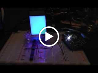
 The same hobby shop also provided me with my plastic solvent adhesive, which it was now time to try out. After a first attempt at thinking I knew better than the instructions failed, I actually followed what the bottle said to do, holding the pieces in place as I wanted and brushing the solvent along the seam. Success! After a few rounds of this, my prototype space with white lining and support was ready to roll. Now, the big test, lighting it up with both the color and white LEDs, for the main body of the space and the color bar, respectively. How did it work? Judge for yourself.


Ignore all the not-interesting LEDs on the protoboard. This testing shows pretty darn good color mixing and distribution, very minimal darkening at the edges due to the supports, and an acceptable amount of hot spotting, all based on lights being driven by the LED driver I plan to use. (Really, the hot spot is even less pronounced in real life than in the photos, as the camera liked picking up the hot spot more than the eye does.) I still need to work on getting my tolerances down for fabricating the pieces, and I need very badly to build some rigs to make the assembly a reliable, repeatable process, but this is looking very promising for getting the kind of effect I want. I also have some ideas about just how deep the various pieces need to be, so I can start doing some actual planning and cutting for pieces that will actually go in the board. Progress is fun!
-
Archives
- November 2012 (2)
- October 2012 (1)
- September 2012 (4)
- July 2012 (2)
- June 2012 (7)
- May 2012 (6)
- April 2012 (5)
-
Categories
-
RSS
Entries RSS
Comments RSS